While it’s typically recommended to use the standard front, top, and right planes when modeling in SOLIDWORKS, there are times when you need to create a sketch or other feature using a plane that doesn’t exist yet. In these scenarios, knowing how to create SOLIDWORKS reference planes comes in handy.
These planes can be at different angles, or offset from a surface, or maybe we need a tangent plane. By creating a new plane, you’re able to sketch from completely new geometry without having an existing model face there.
How to Add SOLIDWORKS Reference Planes
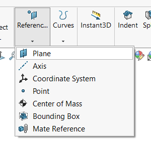
The Reference Plane command is located in the Feature tab, under the Reference Geometry section. This feature lets us create multiple types of planes depending on the types of references we select. The number of references (up to 3 different choices) and types of selections you make (surfaces, edges, or points) will change the type of plane that SOLIDWORKS creates.
 Accessing the Reference Plane command
Creating an Offset Plane

Creating an Offset Reference Plane
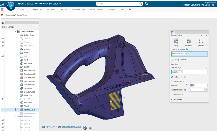
To create an Offset Reference Plane, all you need to select is one flat surface, face, or plane. After selecting the surface, the command will automatically switch to creating an offset plane. From here, you can type in a distance for the offset, and a new plane will be created. Additionally, you can hold the control key, click, and drag an existing plane to quickly create an offset plane.
Creating an Angled Reference Plane
If you select an edge alongside the surface, face, or plane, you will get to create a reference plane at an angle. The newly created SOLIDWORK reference plane will intersect the selected edge at an angle from the flat surface selected. In the PropertyManager, you can dictate the angle at which the reference plane is rotated.

Angled Reference Plane from two selections
How to Create a Reference Plane from 3 Points
Another option for creating reference planes in SOLIDWORKS is by using three different point selections. After making all three selections, a new plane will be created that is coincident with each point. This is one of the few reference planes that requires all three references to be selected.

SOLIDWORKS Reference Plane from three points
How to Make a Mid-Plane Reference
An extremely useful type of reference plane is the Mid-Plane Reference Plane. A mid-plane is created by selecting two parallel surfaces, faces, or planes. The mid-plane will be created at the middle point between the two selections without the end user having to do the calculation themselves or set up any complex relations. If the two selections move, the reference mid-plane will automatically adjust to land in the center between them.

A mid-plane between faces
When you are new to SOLIDWORKS, creating reference planes can be intimidating if you don’t know what types of references to select. There are other types of reference planes that you can create as well, like a tangent plane to a cylindrical surface or a plane that is parallel to your screen. If creating planes is something you find yourself struggling with, our SOLIDWORKS Essentials training class goes even more into detail about exactly how to create these types of planes and more. Our classes are chock-full of helpful tips and tricks to get you modeling faster.
To register for an upcoming SOLIDWORKS Essentials training course, view the course schedule here.
Cloud Software
law
4
Berita Olahraga
Lowongan Kerja
Berita Terkini
Berita Terbaru
Berita Teknologi
Seputar Teknologi
Berita Politik
Resep Masakan
Pendidikan