In the ever-evolving world of engineering simulation, Structural Analysis roles on the 3DEXPERIENCE platform enable engineers to predict and validate the performance of their product designs in a unified cloud-based environment. At its core lies the powerful ABAQUS solver technology that allows users to simulate a wide variety of physics. The role’s ability to seamlessly integrate with SOLIDWORKS bridges the gap between design and analysis.
When simplifying the model for simulation, designers and engineers are looking for ways to accurately mimic the real-world model. Virtual fasteners and connectors are commonly used to represent the connections in an assembly without the undue complexity of meshing the physical bolt or fastener. For example, two panels of sheet metal spot welded together, or a door connected to a frame with a hinge can be simulated using a virtual hinge connection or a point fastener. In other cases, the connection might impose more complicated kinematic constraints, such as constant velocity joints, which transmit constant spinning velocity between misaligned and moving shafts.
This blog details how to define Link Connectors available in Structural Engineer, Structural Performance, or Structural Mechanics engineer roles.

A connector joins two components or entities using either a simple connection or a predefined combination of simple connections.
These connectors are modeled using simple and assembled connector elements, which allow you to define mechanical behaviors for one or more degrees of freedom. Connector elements model the relative translational and rotational behaviors between two parts.
Simulation roles such as Structural Engineer, Structural Performance, and Structural Mechanics Engineer on 3DEXPERIENCE provide two categories of pre-defined connectors based on connection types:
- Translational basic connectors affect translational degrees of freedom at both nodes and might affect rotational degrees of freedom at the first node or at both supports.
- Rotational basic connectors affect only rotational degrees of freedom at both nodes.
You can use predefined connector types to define an Assembled Connector that combines the relative translations and rotations.
The Link Connector maintains a constant position between the entities (or components) it is connecting.

As shown in the figure above, link connection constrains the position of node b, to a constant distance from node a. The constraint force in the link connection acts along the line connecting the two nodes.
The two linkages shown in the SOLIDWORKS model below are replaced using Link Connector available in the Simulia role.

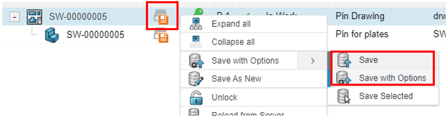
To access Connectors, you can activate the Structural Model creation app either by double-clicking the finite element model representation in the feature tree or selecting the model tab. In the Connector option select ‘Specify’ and then set the translation type to Link. 
There are a few different options available when it comes to specifying the type of rotation. The Coupling type can be set to distributed, kinematic, or structural depending on how you want to couple the displacement and rotational degrees of freedom to the referenced node of coupling.

For any connector type with available components of relative motion, one or more of the connector behaviors such as Plasticity, Elasticity, Damage, Friction, etc. can be available.
The connector behaviors can be defined in an uncoupled or coupled manner. For the uncoupled type, the behavior is prescribed separately for individual available components of relative motion, whereas they can be prescribed simultaneously for coupled systems.
The image below shows the stress results of the analysis with the link connector. The Plot Section tool can be used to display the resultant force and moment.

Virtual connectors, such as the Link Connector, are just one of the many features available in the Simulia roles on the 3DEXPERIENCE platform to help improve structural analysis simulation productivity and make your product designs more resilient.