One of the critical aspects of designing for injection molding is being able to accurately and efficiently perform a split body to prepare for a core and cavity.
SOLIDWORKS xDesign has purpose-built tools to help split your models to better prepare for mold design purposes. Combine the Split Body command with Geometrical Sets, and you’re well on your way to designing faster and manufacturing faster.
What is the Split Body Command?
The Split Body command in SOLIDWORKS xDesign is one of the most essential CAD tools for designing mechanical parts, helping users separate bodies and features efficiently. Let’s take a look at this Jigsaw product, as we have throughout the Intermediate and advanced stages of this SOLIDWORKS xDesign blog.
How to Use the Split Body Command
The outer enclosure of our jigsaw is likely injection molded. The reason is that this plastic piece has a generally constant wall thickness, is relatively thin-walled, needs mass production, and has complex geometry. The Split command in SOLIDWORKS xDesign lets users separate bodies and features with ease.
In this example, we’ll focus on splitting the outer body, which was originally modeled in xShape, a cloud-based CAD tool.
Create the Splitting Geometry
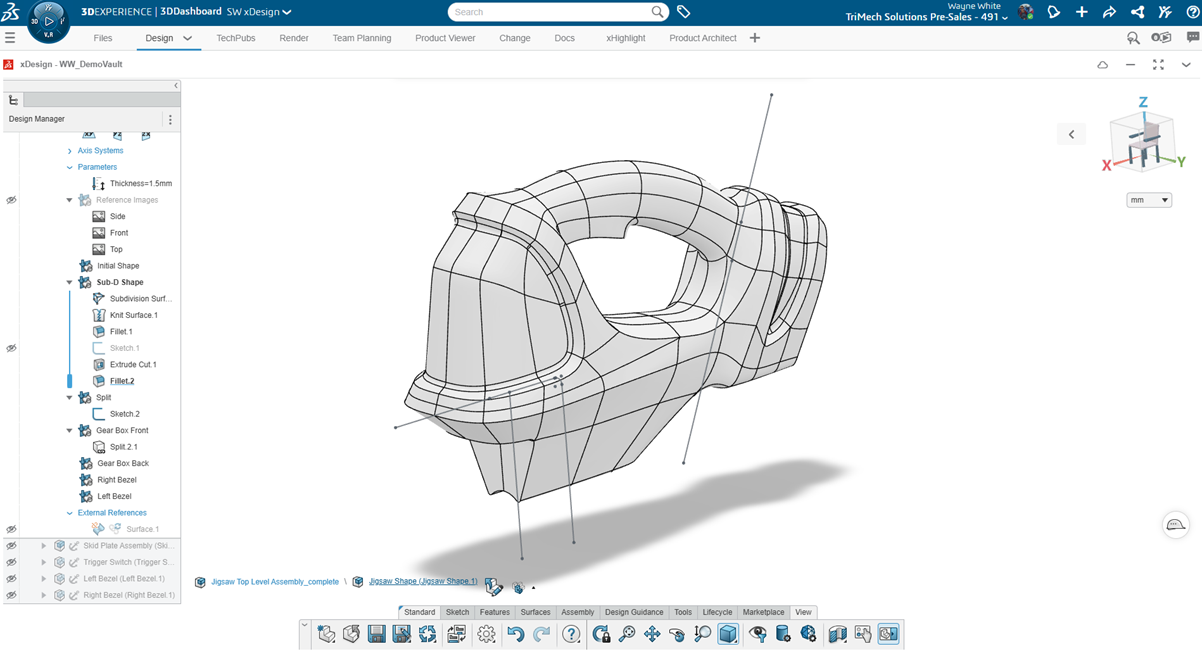
In the image below, we have a pretty basic sketch in the model. We imagine these sketch lines will do the cutting, or in this case, the splitting of our body. We imagine that these lines create an extruded surface that infinitely extends without bound, which will be our cutting tool.
 Using sketches to define the split boundary
Activate the Split Body Command
We activate the Split Body command from the action bar. The reason we do a split is that when we make these parts, the items will be separate geometry with separate tooling.
There is a Split Face command as well that can split faces for appearance operations, decals, or textures. However, splitting faces doesn’t create separate physical parts that have separate tooling instructions.

Using the Split Body command in SOLIDWORKS xDesign
In the example above, we chose the Project option, used the main body of the part to split, and the sketches to split the body. I will also split the geometry about the zx plane (right down the middle) to create a left and right-hand version of the main body.
Using Geometrical Sets for Tooling Splits
The next thing that we want to do is create separate physical bodies that we may want to create tooling for or 3D print. That’s the work of the Make Component command and ordered geometrical sets in SOLIDWORKS xDesign.
How to Use the Make Component Command
The Make Component command allows us to create separate bodies from the splits that we can physically hold if we were to 3D print these pieces. This command creates the different bodies that we can hold and manufacture separately.

Activating the Make Component command
Below, I’ll create a linked body and define the name. The Linked Body option is nice because it creates a dependency back to the main set of features. If those features or geometry change, we expect the tooling to update.

Creating the geometrical set as a Linked Body
Next, we make a component for the Right Bezel body. As we can see in the tree, this is a separate physical product (separate object in 3DEXPERIENCE) also signaled from a different Name in 3DEXPERIENCE with the prd syntax. We can see under its design features- split 2.1- indicating a reference back to the Split.2 master body.
Finally, if we isolate the right bezel, we can see the part is solid throughout. At this point, the body is ready for the final stages, shell, ribs, pockets, or other post-processing. Those are the final features necessary to have a mold made to specification.

Isolated half of the jigsaw body
Unleashing Creativity with SOLIDWORKS xDesign
Utilizing the Split command and ordered geometrical sets in SOLIDWORKS xDesign is a powerful method to get the final details onto your part design. The process is quite similar to 3D CAD techniques of the past and quite intuitive to those who have been using these tools for some time.
Cloud-based design tools launch you into the future and keep you on the cutting-edge of technology, allowing your team to unleash their creativity. With SOLIDWORKS xDesign, your team stays up to date with the latest design changes and can focus on what matters.
Want to learn more about the best-in-class design tools on 3DEXPERIENCE? Click here.
News
Berita Teknologi
Berita Olahraga
Sports news
sports
Motivation
football prediction
technology
Berita Technologi
Berita Terkini
Tempat Wisata
News Flash
Football
Gaming
Game News
Gamers
Jasa Artikel
Jasa Backlink
Agen234
Agen234
Agen234
Resep
Cek Ongkir Cargo
Download Film


